A lifepo4 battery pack stores electrical energy through multiple lithium iron phosphate cells connected in series, parallel, or both. Its chemistry is known for strong thermal stability, long cycle life, and dependable performance. Yet the pack is more than a group of cells. It also includes a battery management system, wiring, fuses, insulation, terminals, and a protective enclosure.
Battery scientist Dr. Jeff Dahn has described lithium-ion technology plainly: “The lithium-ion battery is a very complex device.” That warning matters here. A properly designed lifepo4 battery pack monitors cell voltage, temperature, charging current, and discharge conditions. The management system can disconnect the load when a cell reaches an unsafe limit. It can also balance cells, although balancing quality varies between manufacturers.
The working process is easier to picture inside a small electric vehicle or solar cabinet. During charging, lithium ions move toward the negative electrode. During discharge, they move back while electrons travel through the external circuit. That electron flow powers an inverter, motor, or appliance. Simple in theory.
Real systems are less perfect.
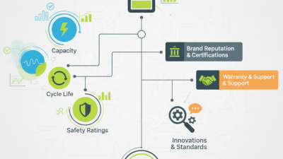
Cold temperatures can reduce charging performance. Poor connections may create heat at the terminals. An oversized inverter can also stress the pack beyond its intended design. For this reason, evaluating a lifepo4 battery pack requires more than reading its advertised capacity. Cell grade, continuous current ratings, cycle testing, warranty terms, and enclosure quality deserve close attention. The following sections explain each part and show how the complete pack delivers usable, controlled energy.
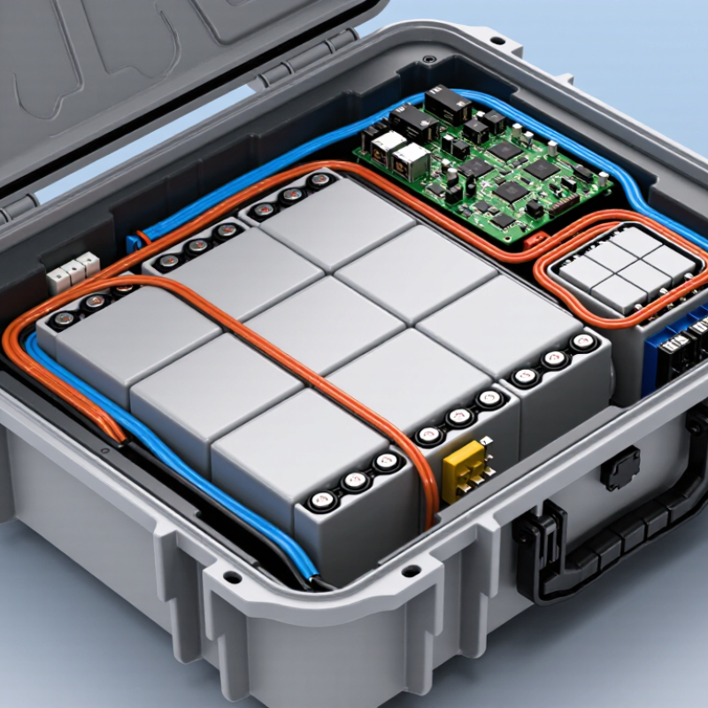
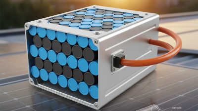
A LiFePO4 battery pack combines multiple lithium iron phosphate cells into one controlled energy system. Each cell has a nominal voltage of about 3.2 volts. Four cells connected in series create a 12.8-volt pack. Parallel connections increase capacity, measured in ampere-hours.
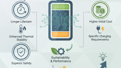
Inside the pack, the cells work with busbars, fuses, sensors, an enclosure, and a battery management system. During charging, lithium ions move toward the negative electrode. During use, they move back while releasing electrical energy. The management system monitors voltage, temperature, and current. It can balance cells and disconnect the pack during unsafe conditions. The chemistry usually offers strong thermal stability and long service life, but its energy density is often lower than nickel-rich alternatives. The International Energy Agency reported that LFP batteries represented nearly 40% of electric vehicle batteries deployed globally in 2023. BloombergNEF reported an average lithium-ion pack price of 139 dollars per kilowatt-hour in 2023, showing why pack design remains commercially important.
Tips: Check the pack’s continuous current rating, not only its capacity. A 100 Ah pack may still fail under a heavy load. Keep charging limits within the manufacturer’s specifications. Real-world life depends on heat, charging habits, cell matching, and installation quality. I used to view capacity as the main measure; that was too simple. Wiring losses and poor balancing can quietly reduce usable energy.
A LiFePO4 battery pack is more than a group of lithium iron phosphate cells. Its performance depends on how each component works with the others. The International Energy Agency reported that LFP batteries represented nearly 40% of the global electric vehicle battery market in 2023. This growth reflects their strong thermal stability, long cycle life, and lower material cost.
The cells store energy. They may use prismatic, cylindrical, or pouch formats. A battery management system monitors cell voltage, current, and temperature. It also balances cells during charging. Without accurate balancing, one weak cell can limit the entire pack. Small differences matter. Copper busbars connect the cells and carry electrical current. A fuse or contactor interrupts power during a severe fault. These protective parts are easy to overlook, yet they protect both equipment and users.
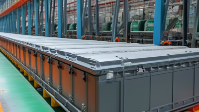
The enclosure provides mechanical support and helps resist dust, vibration, and moisture. Some packs include thermal sensors, cooling plates, or air channels. LiFePO4 cells usually generate less heat than several other lithium chemistries, but they still need controlled operating conditions. A charger and power-control circuit regulate energy entering the pack. According to the U.S. Department of Energy’s Battery500 research program, improving energy density remains a major industry target. That goal can create trade-offs. More compact designs may reduce cooling space or make servicing harder. A reliable pack therefore needs careful electrical design, practical thermal control, and consistent quality testing.
| Component | Primary Function | Typical Electrical Data | How It Works in the Pack | Key Design Considerations |
|---|---|---|---|---|
| LiFePO4 Battery Cells | Store and release electrical energy through reversible lithium-ion reactions. |
Nominal voltage: 3.2 V per cell Charge limit: approximately 3.65 V per cell Common discharge cutoff: approximately 2.5 V per cell |
Cells are connected in series to increase voltage and in parallel to increase capacity and current capability. | Cell matching, temperature, allowable current, state of charge, and mechanical compression affect service life and safety. |
| Series and Parallel Cell Arrangement | Defines the pack voltage, capacity, and available current. |
Series connection: voltages add together Parallel connection: ampere-hours and current capability add together Example: 4S provides about 12.8 V nominal |
A 4S configuration uses four 3.2 V cells or cell groups in series to create a nominal 12.8 V battery pack. | All series groups should remain balanced so that no individual cell reaches an unsafe voltage before the others. |
| Battery Management System (BMS) | Monitors and protects the cells during charging, discharging, and storage. |
Monitors cell voltage, pack current, and temperature Protection functions include overcharge, over-discharge, overcurrent, short circuit, and overheating |
The BMS disconnects or limits the current path when measured conditions exceed configured safety thresholds. | The BMS rating should match the pack voltage, continuous current, peak current, charging method, and number of series cells. |
| Cell-Balancing Circuit | Reduces voltage differences between cells or series groups. |
Passive balancing commonly dissipates excess energy as heat Active balancing transfers energy between cells |
Balancing helps keep series-connected cells within a similar state of charge, especially near the end of charging. | Balancing does not repair a weak cell; large or recurring voltage differences may indicate cell mismatch or aging. |
| Busbars and Interconnects | Carry current between cells, parallel groups, the BMS, and external terminals. |
Low-resistance conductive paths Current rating must exceed the intended continuous and peak load |
Busbars and welded or bolted connections create the low-resistance electrical network inside the pack. | Correct conductor size, secure fastening, insulation, and corrosion resistance are essential to limit heat and voltage drop. |
| Temperature Sensors | Measure cell, busbar, or enclosure temperature. |
Common sensor type: NTC thermistor Used for charge and discharge temperature protection |
Temperature readings are sent to the BMS, which can reduce current or disconnect the pack when temperature limits are exceeded. | Sensor placement should represent the hottest likely location, such as the center of a dense cell group or near high-current connections. |
| Fuse or Circuit Breaker | Provides an independent layer of protection against severe overcurrent and short circuits. | Selected according to system voltage, continuous current, interrupt rating, and expected fault current | The protective device opens the main current path when a fault exceeds its specified operating limit. | It should be installed close to the positive battery terminal and coordinated with the BMS and external wiring. |
| Main Terminals and Power Cables | Connect the battery pack to the charger, inverter, motor controller, or load. | Cable capacity depends on current, length, insulation rating, and allowable voltage drop | Terminals provide the positive and negative interfaces through which energy enters or leaves the pack. | Polarity, connector security, cable sizing, insulation clearance, and strain relief must be verified before operation. |
| Insulation and Electrical Barriers | Prevent unintended contact, short circuits, and current leakage. | Includes insulating sheets, sleeves, separators, terminal covers, and protective barriers | Insulation separates conductive parts from one another and from the enclosure throughout charging and discharging. | Materials must withstand the expected voltage, temperature, vibration, and mechanical movement inside the pack. |
| Mechanical Enclosure | Protects internal components from impact, dust, moisture, vibration, and accidental contact. | May include metal or polymer housing, cell holders, compression plates, seals, and mounting points | The enclosure maintains structural alignment and provides a controlled environment for the cells and electronics. | It should provide adequate rigidity, ventilation or heat dissipation where required, ingress protection, and service access. |
| Charging System | Restores energy to the cells using a controlled charging profile. |
LiFePO4 charging commonly uses a constant-current/constant-voltage profile The charger must match the pack's series count and charge-voltage limit |
The charger supplies current until the pack reaches its voltage limit, then holds that voltage while current gradually decreases. | Charging below freezing can damage lithium-ion cells unless the pack has suitable low-temperature control or heating. |
| Monitoring and Communication Interface | Reports voltage, current, temperature, state of charge, alarms, and protection events. |
May use a display, wired data connection, or wireless connection Available measurements depend on the BMS design |
The interface presents operating information and may allow authorized configuration or system-level control. | Displayed state-of-charge values are estimates based on current measurement, voltage behavior, and accumulated battery data. |
A LiFePO4 battery pack stores electrical energy through reversible chemical movement inside its cells. Each cell contains a lithium iron phosphate cathode, a graphite anode, an electrolyte, and a separator. The separator keeps the electrodes apart while allowing lithium ions to pass through.
During charging, an external charger pushes lithium ions from the cathode toward the graphite anode. Electrons travel through the charging circuit and collect at the anode. The battery therefore stores energy in the chemical balance between both electrodes. During use, lithium ions move back toward the cathode. Electrons leave the anode, flow through the device, and produce useful power.
The process is controlled, not magical. A cell usually provides about 3.2 volts, so several cells connect in series for higher voltage. Parallel groups increase available capacity and current. A battery management system monitors cell voltage, temperature, and charging conditions. It can disconnect the circuit when a cell becomes unsafe or unbalanced. In practical installations, strong terminals and suitable cables also matter.
A simple analogy helps. Think of ions as workers crossing a guarded bridge. Yet the analogy is incomplete. Real cells experience resistance, heat, aging, and small differences between individual cells. Cold temperatures can slow ion movement, while excessive current can stress the internal materials. Careful charging improves reliability, but it cannot stop gradual capacity loss.
This is where real testing matters.
A LiFePO4 battery pack combines multiple lithium iron phosphate cells to store electrical energy. Its battery management system, or BMS, acts as the pack’s control center. It measures cell voltage, current, and temperature many times each second. These readings help the BMS maintain safe and balanced operation.
During charging, the BMS can reduce or stop current when a cell reaches its voltage limit. During use, it disconnects the load if voltage falls too low. It also responds to overheating, excessive current, and short-circuit conditions. Cell balancing is important because small voltage differences grow over repeated cycles. Passive balancing may remove surplus energy as heat, while active systems can transfer energy between cells. Both approaches have practical limits.
Real-world testing shows that sensor placement matters. A loose temperature sensor may report a safer condition than the cell actually has. No controller is perfect. The BMS cannot repair damaged cells or compensate for poor wiring. It only reacts to the information it receives, so accurate sensors and secure connections remain essential.
Tips: Keep the pack dry and properly ventilated. Use a charger matched to the pack’s voltage and chemistry. Check unusual heat, swelling, odor, or sudden capacity loss promptly. Record operating temperatures during demanding use. This simple habit can reveal problems earlier.
A LiFePO4 battery pack uses lithium iron phosphate cells to store and release electrical energy. A typical 12.8-volt pack contains four cells connected in series. During charging, lithium ions move toward the negative electrode. During use, they move back and produce power.
Charging requires the correct lithium battery profile, usually constant current followed by constant voltage. A charger designed for lead-acid batteries may use an unsuitable voltage or maintenance cycle. That mistake can reduce battery life. Check the pack’s datasheet before connecting anything. The battery management system monitors cell voltage, temperature, and current. It can disconnect the pack during abnormal conditions. Still, it should not replace careful installation.
Keep the battery dry, secure, and away from direct heat. Do not charge it below 0°C unless the system specifically allows low-temperature charging. Use a fuse near the positive terminal. Inspect cables for loose terminals, cuts, or unusual warmth. No battery is risk-free. LiFePO4 chemistry is generally more thermally stable than several other lithium types, but damage, overcharging, or poor wiring can still create hazards.
These packs commonly power recreational vehicles, small boats, solar storage systems, emergency backup units, and mobility equipment. They offer steady voltage and useful cycle life. In practice, performance depends on temperature, charging habits, load size, and storage conditions. I would not treat the published cycle count as a promise; real installations are less controlled. A partly charged battery stored in a cool, dry place is often more practical than chasing perfect numbers.
A LiFePO4 battery pack connects multiple 3.2 V nominal cells in series to increase voltage. The chart compares typical nominal voltage with the recommended maximum charging voltage for common pack configurations.
LiFePO4 batteries are commonly charged with a constant-current/constant-voltage profile. A battery-management system helps balance cells and protects against overcharge, over-discharge, excessive current, and abnormal temperature. Typical applications include solar energy storage, electric mobility, backup power, and recreational vehicles.